Unit2: THE PHYSICAL LAYER
TRASMISSION MEDIA: What is
Transmission media?
Transmission media is a communication
channel that carries the information from the sender to the receiver. Data is
transmitted through the electromagnetic signals.
The main functionality of the
transmission media is to carry the information in the form of bits
through LAN(Local Area Network).
It is a physical path between
transmitter and receiver in data communication.
In a copper-based network, the bits in
the form of electrical signals.
In a fibre based network, the bits in
the form of light pulses.
In OSI(Open System Interconnection)
phase, transmission media supports the Layer 1. Therefore, it is considered to
be as a Layer 1 component.
The electrical signals can be sent
through the copper wire, fibre optics, atmosphere, water, and vacuum.
The characteristics and quality of data
transmission are determined by the characteristics of medium and signal.
Transmission media is of two types are
wired media and wireless media. In wired media, medium characteristics are more
important whereas, in wireless media, signal characteristics are more
important.
Different transmission media have
different properties such as bandwidth, delay, cost and ease of installation
and maintenance.
The transmission media is available in
the lowest layer of the OSI reference model, i.e., Physical layer.
Some factors need to be considered for
designing the transmission media:
Bandwidth: All the factors are
remaining constant, the greater the bandwidth of a medium, the higher the data
transmission rate of a signal.
Transmission impairment: When the
received signal is not identical to the transmitted one due to the transmission
impairment. The quality of the signals will get destroyed due to transmission
impairment.
Interference: An interference is
defined as the process of disrupting a signal when it travels over a
communication medium on the addition of some unwanted signal.
Causes Of Transmission Impairment:

Attenuation: Attenuation means the loss of energy, i.e., the strength of the signal decreases with increasing the distance which causes the loss of energy.
Distortion: Distortion occurs when there is a change in the shape of the signal. This type of distortion is examined from different signals having different frequencies. Each frequency component has its own propagation speed, so they reach at a different time which leads to the delay distortion.
Noise: When data is travelled over a transmission medium, some unwanted signal is added to it which creates the noise.
Classification Of Transmission Media:


It is defined as the physical medium
through which the signals are transmitted. It is also known as Bounded media.
Types Of Guided media:
Twisted pair:
Twisted pair is a physical media made up
of a pair of cables twisted with each other. A twisted pair cable is cheap as
compared to other transmission media. Installation of the twisted pair cable is
easy, and it is a lightweight cable. The frequency range for twisted pair cable
is from 0 to 3.5KHz.
A twisted pair consists of two insulated
copper wires arranged in a regular spiral pattern.
The degree of reduction in noise
interference is determined by the number of turns per foot. Increasing the
number of turns per foot decreases noise interference.

Types
of Twisted pair:

Unshielded Twisted Pair:
An unshielded twisted pair is widely
used in telecommunication. Following are the categories of the unshielded
twisted pair cable:
Category 1: Category 1 is used for
telephone lines that have low-speed data.
Category 2: It can support upto
4Mbps.
Category 3: It can support upto
16Mbps.
Category 4: It can support upto
20Mbps. Therefore, it can be used for long-distance communication.
Category 5: It can support upto
200Mbps.
Advantages Of Unshielded Twisted Pair:
It is cheap.
Installation of the unshielded twisted
pair is easy.
It can be used for high-speed LAN.
Disadvantage:
This cable can only be used for shorter
distances because of attenuation.
Shielded Twisted Pair
A shielded twisted pair is a cable that
contains the mesh surrounding the wire that allows the higher transmission
rate.
Characteristics Of Shielded Twisted
Pair:
The cost of the shielded twisted pair
cable is not very high and not very low.
An installation of STP is easy.
It has higher capacity as compared to
unshielded twisted pair cable.
It has a higher attenuation.
It is shielded that provides the higher
data transmission rate.
Disadvantages
o Comparatively
difficult to install and manufacture
o Bulky
It is more expensive as compared to UTP
and coaxial cable.
It has a higher attenuation rate.
COAXIAL CABLE:
Coaxial cable is very commonly used
transmission media, for example, TV wire is usually a coaxial cable.
The name of the cable is coaxial as it
contains two conductors parallel to each other.
It has a higher frequency as compared to
Twisted pair cable.
The inner conductor of the coaxial cable
is made up of copper, and the outer conductor is made up of copper mesh. The
middle core is made up of non-conductive cover that separates the inner
conductor from the outer conductor.
The middle core is responsible for the
data transferring whereas the copper mesh prevents from
the EMI(Electromagnetic interference).

Coaxial cable is of two types:
Baseband transmission: It is
defined as the process of transmitting a single signal at high speed.
Broadband transmission: It is
defined as the process of transmitting multiple signals simultaneously.
Advantages Of Coaxial cable:
The data can be transmitted at high
speed.
It has better shielding as compared to
twisted pair cable.
It provides higher bandwidth.
Disadvantages Of Coaxial cable:
o It is more expensive
as compared to twisted pair cable.
o If any fault occurs
in the cable causes the failure in the entire network
OPTICAL FIBER: Fibre Optic
Fibre optic cable is a cable that uses
electrical signals for communication.
Fibre optic is a cable that holds the
optical fibres coated in plastic that are used to send the data by pulses of
light.
The plastic coating protects the optical
fibres from heat, cold, electromagnetic interference from other types of
wiring.
Fibre optics provide faster data
transmission than copper wires.
Diagrammatic representation of fibre
optic cable:

Basic elements of Fibre optic cable:
Core: The optical fibre consists of
a narrow strand of glass or plastic known as a core. A core is a light
transmission area of the fibre. The more the area of the core, the more light
will be transmitted into the fibre.
Cladding: The concentric layer of
glass is known as cladding. The main functionality of the cladding is to
provide the lower refractive index at the core interface as to cause the
reflection within the core so that the light waves are transmitted through the
fibre.
Jacket: The protective coating
consisting of plastic is known as a jacket. The main purpose of a jacket is to
preserve the fibre strength, absorb shock and extra fibre protection.
Following are the advantages of fibre
optic cable over copper:
Greater Bandwidth: The fibre optic
cable provides more bandwidth as compared copper. Therefore, the fibre optic
carries more data as compared to copper cable.
Faster speed: Fibre optic cable
carries the data in the form of light. This allows the fibre optic cable to
carry the signals at a higher speed.
Longer distances: The fibre optic
cable carries the data at a longer distance as compared to copper cable.
Better reliability: The fibre optic
cable is more reliable than the copper cable as it is immune to any temperature
changes while it can cause obstruct in the connectivity of copper cable.
Thinner and Sturdier: Fibre optic
cable is thinner and lighter in weight so it can withstand more pull
pressure than copper cable.
RADIO
TRANSMISSION:
UnGuided Transmission
An unguided transmission transmits the
electromagnetic waves without using any physical medium. Therefore it is also
known as wireless transmission.
In unguided media, air is the media
through which the electromagnetic energy can flow easily.
Unguided transmission is broadly
classified into three categories:
Radio waves
Radio waves are the electromagnetic
waves that are transmitted in all the directions of free space.
Radio waves are omnidirectional, i.e.,
the signals are propagated in all the directions.
The range in frequencies of radio waves
is from 3Khz to 1 khz.
In the case of radio waves, the sending
and receiving antenna are not aligned, i.e., the wave sent by the sending
antenna can be received by any receiving antenna.
An example of the radio wave is FM
radio.
 Applications Of Radio waves: A Radio wave is useful for multicasting
when there is one sender and many receivers. An FM radio, television, cordless phones
are examples of a radio wave. Advantages Of Radio transmission: Radio transmission is mainly used for
wide area networks and mobile cellular phones. Radio waves cover a large area, and they
can penetrate the walls. Radio transmission provides a higher
transmission rate. MICROWAVES :
 Microwaves are of two types: Terrestrial microwave Satellite microwave communication. Terrestrial Microwave Transmission Terrestrial Microwave transmission is a
technology that transmits the focused beam of a radio signal from one
ground-based microwave transmission antenna to another. Microwaves are the electromagnetic waves
having the frequency in the range from 1GHz to 1000 GHz. Microwaves are unidirectional as the
sending and receiving antenna is to be aligned, i.e., the waves sent by the
sending antenna are narrowly focussed. In this case, antennas are mounted on
the towers to send a beam to another antenna which is km away. It works on the line of sight
transmission, i.e., the antennas mounted on the towers are the direct sight of
each other. Characteristics of Microwave: Frequency range: The frequency
range of terrestrial microwave is from 4-6 GHz to 21-23 GHz. Bandwidth: It supports the
bandwidth from 1 to 10 Mbps. Short distance: It is inexpensive
for short distance. Long distance: It is expensive as
it requires a higher tower for a longer distance. Attenuation: Attenuation
means loss of signal. It is affected by environmental conditions and antenna
size. Advantages Of Microwave:
Satellite Microwave
Communication
How Does Satellite work? The satellite accepts the
signal that is transmitted from the earth station, and it amplifies the signal.
The amplified signal is retransmitted to another earth station. Advantages Of Satellite
Microwave Communication:
Disadvantages Of Satellite
Microwave Communication:
INFRARED
TRANSMISSION: Infrared
Characteristics Of
Infrared:
SWITCHING: When a user accesses the internet or another computer
network outside their immediate location, messages are sent through the network
of transmission media. This technique of transferring the information from one
computer network to another network is known as switching.
Why is
Switching Concept required? Switching
concept is developed because of the following reasons:
Advantages
of Switching:
Disadvantages
of Switching:
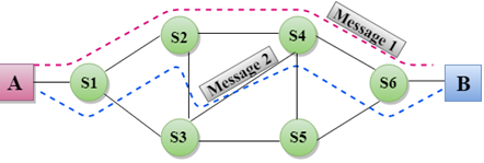
MESSAGE SWITCHING: Switching techniques In large networks, there can be multiple paths
from sender to receiver. The switching technique will decide the best route for
data transmission. Switching technique is used to connect the
systems for making one-to-one communication. Classification Of Switching Techniques
|

Message Switching
Message Switching is a switching
technique in which a message is transferred as a complete unit and routed
through intermediate nodes at which it is stored and forwarded.
In Message Switching technique, there is
no establishment of a dedicated path between the sender and receiver.
The destination address is appended to
the message. Message Switching provides a dynamic routing as the message is
routed through the intermediate nodes based on the information available in the
message.
Message switches are programmed in such
a way so that they can provide the most efficient routes.
Each and every node stores the entire
message and then forward it to the next node. This type of network is known
as store and forward network.
Message switching treats each message as
an independent entity.
Advantages Of Message Switching
Data channels are shared among the
communicating devices that improve the efficiency of using available bandwidth.
Traffic congestion can be reduced
because the message is temporarily stored in the nodes.
Message priority can be used to manage
the network.
The size of the message which is sent
over the network can be varied. Therefore, it supports the data of unlimited
size.
Disadvantages Of Message Switching
The message switches must be equipped
with sufficient storage to enable them to store the messages until the message
is forwarded.
The Long delay can occur due to the
storing and forwarding facility provided by the message switching technique.
MULTIPLEXING: What is Multiplexing?
Multiplexing is a technique used to
combine and send the multiple data streams over a single medium. The process of
combining the data streams is known as multiplexing and hardware used for
multiplexing is known as a multiplexer.
Multiplexing is achieved by using a
device called Multiplexer (MUX) that combines n input lines to generate a
single output line. Multiplexing follows many-to-one, i.e., n input lines and
one output line.
Demultiplexing is achieved by using a
device called Demultiplexer (DEMUX) available at the receiving end. DEMUX
separates a signal into its component signals (one input and n outputs).
Therefore, we can say that demultiplexing follows the one-to-many approach.
Why Multiplexing?
The transmission medium is used to send
the signal from sender to receiver. The medium can only have one signal at a
time.
If there are multiple signals to share
one medium, then the medium must be divided in such a way that each signal is
given some portion of the available bandwidth. For example: If there are 10
signals and bandwidth of medium is100 units, then the 10 unit is shared by each
signal.
When multiple signals share the common
medium, there is a possibility of collision. Multiplexing concept is used to
avoid such collision.
Transmission services are very
expensive.
History of Multiplexing
Multiplexing technique is widely used in
telecommunications in which several telephone calls are carried through a
single wire.
Multiplexing originated in telegraphy in
the early 1870s and is now widely used in communication.
George Owen Squier developed
the telephone carrier multiplexing in 1910.
Concept of Multiplexing

The 'n' input lines are transmitted through a multiplexer and multiplexer combines the signals to form a composite signal.
The composite signal is passed through a Demultiplexer and demultiplexer separates a signal to component signals and transfers them to their respective destinations.
Advantages of Multiplexing:
More than one signal can be sent over a single medium.
The bandwidth of a medium can be utilized effectively.
Multiplexing Techniques
Multiplexing techniques can be classified as:

Frequency-division Multiplexing (FDM)
It is an analog technique.
Frequency Division Multiplexing is
a technique in which the available bandwidth of a single transmission medium is
subdivided into several channels.

In the above diagram, a single transmission medium is subdivided into several frequency channels, and each frequency channel is given to different devices. Device 1 has a frequency channel of range from 1 to 5.
The input signals are translated into frequency bands by using modulation techniques, and they are combined by a multiplexer to form a composite signal.
The main aim of the FDM is to subdivide the available bandwidth into different frequency channels and allocate them to different devices.
Using the modulation technique, the input signals are transmitted into frequency bands and then combined to form a composite signal.
The carriers which are used for modulating the signals are known as sub-carriers. They are represented as f1,f2..fn.
FDM is mainly used in radio broadcasts and TV networks.
Advantages Of FDM:
FDM is used for analog signals.
FDM process is very simple and easy
modulation.
A Large number of signals can be sent
through an FDM simultaneously.
It does not require any synchronization
between sender and receiver.
Disadvantages Of FDM:
FDM technique is used only when
low-speed channels are required.
It suffers the problem of crosstalk.
A Large number of modulators are
required.
It requires a high bandwidth channel.
Applications Of FDM:
FDM is commonly used in TV networks.
It is used in FM and AM broadcasting.
Each FM radio station has different frequencies, and they are multiplexed to
form a composite signal. The multiplexed signal is transmitted in the air.
Wavelength Division Multiplexing (WDM)

Wavelength Division Multiplexing is same as FDM except that the optical signals are transmitted through the fibre optic cable.
WDM is used on fibre optics to increase the capacity of a single fibre.
It is used to utilize the high data rate capability of fibre optic cable.
It is an analog multiplexing technique.
Optical signals from different source are combined to form a wider band of light with the help of multiplexer.
At the receiving end, demultiplexer separates the signals to transmit them to their respective destinations.
Multiplexing and Demultiplexing can be achieved by using a prism.
Prism can perform a role of multiplexer by combining the various optical signals to form a composite signal, and the composite signal is transmitted through a fibre optical cable.
Prism also performs a reverse operation, i.e., demultiplexing the signal.

Time Division Multiplexing
It is a digital technique.
In Frequency Division Multiplexing
Technique, all signals operate at the same time with different frequency, but
in case of Time Division Multiplexing technique, all signals operate at the
same frequency with different time.
In Time Division Multiplexing technique,
the total time available in the channel is distributed among different users.
Therefore, each user is allocated with different time interval known as a Time
slot at which data is to be transmitted by the sender.
A user takes control of the channel for
a fixed amount of time.
In Time Division Multiplexing technique,
data is not transmitted simultaneously rather the data is transmitted
one-by-one.
In TDM, the signal is transmitted in the
form of frames. Frames contain a cycle of time slots in which each frame
contains one or more slots dedicated to each user.
It can be used to multiplex both digital
and analog signals but mainly used to multiplex digital signals.
There are two types of TDM:
Synchronous TDM
Asynchronous TDM
Synchronous TDM
A Synchronous TDM is a technique in
which time slot is preassigned to every device.
In Synchronous TDM, each device is given
some time slot irrespective of the fact that the device contains the data or
not.
If the device does not have any data,
then the slot will remain empty.
In Synchronous TDM, signals are sent in
the form of frames. Time slots are organized in the form of frames. If a device
does not have data for a particular time slot, then the empty slot will be
transmitted.
The most popular Synchronous TDM are T-1
multiplexing, ISDN multiplexing, and SONET multiplexing.
If there are n devices, then there are n
slots.

Concept Of
Synchronous TDM
- .
In the above figure, the Synchronous TDM
technique is implemented. Each device is allocated with some time slot. The
time slots are transmitted irrespective of whether the sender has data to send
or not.
Disadvantages Of Synchronous TDM:
The capacity of the channel is not fully
utilized as the empty slots are also transmitted which is having no data. In
the above figure, the first frame is completely filled, but in the last two
frames, some slots are empty. Therefore, we can say that the capacity of the
channel is not utilized efficiently.
The speed of the transmission medium
should be greater than the total speed of the input lines. An alternative
approach to the Synchronous TDM is Asynchronous Time Division Multiplexing.
Asynchronous TDM
An asynchronous TDM is also known as
Statistical TDM.
An asynchronous TDM is a technique in
which time slots are not fixed as in the case of Synchronous TDM. Time slots
are allocated to only those devices which have the data to send. Therefore, we
can say that Asynchronous Time Division multiplexor transmits only the data
from active workstations.
An asynchronous TDM technique
dynamically allocates the time slots to the devices.
In Asynchronous TDM, total speed of the
input lines can be greater than the capacity of the channel.
Asynchronous Time Division multiplexor
accepts the incoming data streams and creates a frame that contains only data
with no empty slots.
In Asynchronous TDM, each slot contains
an address part that identifies the source of the data
![]()
The difference between Asynchronous TDM and Synchronous TDM is that many slots in Synchronous TDM are unutilized, but in Asynchronous TDM, slots are fully utilized. This leads to the smaller transmission time and efficient utilization of the capacity of the channel.
In Synchronous TDM, if there are n sending devices, then there are n time slots. In Asynchronous TDM, if there are n sending devices, then there are m time slots where m is less than n (m<n).
The number of slots in a frame depends on the statistical analysis of the number of input lines.
Concept Of Asynchronous TDM

In the above diagram, there are 4
devices, but only two devices are sending the data, i.e., A and C. Therefore,
the data of A and C are only transmitted through the transmission line.
Frame of above diagram can be
represented as:

The above
figure shows that the data part contains the address to determine the source of
the data.
No comments:
Post a Comment